

Welcome to part 2 of the satellite dish teardown. Today we will be looking at the feed horn of the satellite dish that has spent the last 10 years being an ornament on my house. This will include looking at the radome, the shape of the feed horn and the internal features to make it work well. If you want to read part 1 where we look at the dish installation as a whole please have a look at: https://swamphen.co.uk/new-blog/2019/6/24/satellite-dish-teardown

This is a close up of the feed horn and receiver that is at the focal point of the paraboloid of the offset fed parabolic reflector satellite dish. It takes the electromagnetic signal collected by the dish, converts the free space electromagnetic signal to an electric current to be processed in the circuit board of the receiver and transmits the signal to your TV set.
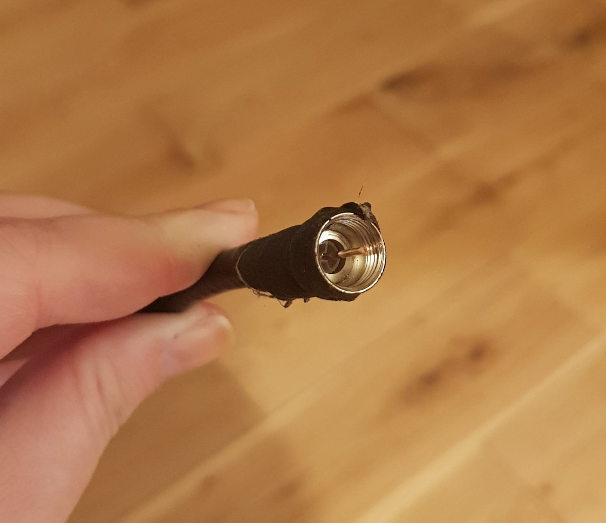
Having removed the feed and receiver unit from the feed arm you can see that the final processed signal comes out at the back of the feed unit. A male SMA cable connects to a standard coax cable, which is then routed into your house.

The next piece to be removed was the radome, which is made of plastic and was snap fitted very tightly over the end of the feed horn. This will stop any moisture or insects getting into the feedhorn. If I have learnt anything working on outdoor test sites, it is that spiders love to make their homes in feed horns. Secondly, that the smell of roasted spider is not something you want to be inhaling. It is interesting to note that the radome is slightly convex, so that there is the same distance from the radome to the back of the feed horn for each of the rays, which minimises the impact of the radome on the signal. Also included in this photo are some cobwebs from the re-homed spiders for authenticity and showing that they didn’t make it inside the feed horn.

The radome is made from injection moulded plastic, the injection point can be clearly seen in the centre of the radome. This will cause some perturbation in the signal, but this will be at a low level and be acceptable to the overall system. Injection moulding is a common process for mass produced parts and to remove the injection point, so the final radome is a constant thickness all the way across, will make the part more expensive to produce with a small improvement in performance.

Looking at the exposed feed horn there are several features immediately apparent. The sides are sloped, there are ridges on the inside of the feed horn, and metal rods sticking into the space in the middle. The feed horn seems to be made from metal casting as it has some small defects that can be seen at the end of the feed horn. It is probably lost wax casting, as there are some holes that go all the way through the casting which do not appear to be post machined. Metal casting is a common choice for mass production metal parts and is extensively used for waveguide parts.
The sloped sides flare the circular wavegude (the cylindrical part with a fixed diameter at the back of the feed horn) into a feed horn. This flaring is used to match the impedance of wave in the wave guide to the impedance of free space. Therefore, using a feed horn allows the electromagnetic energy to radiate out into space with minimal disturbances and reflections.

The feed horn itself is a corrugated elliptical feed horn. The outside of the horn looks conical, but the elliptical shape is formed on the inside. This feed horn is elliptical to match the shape of the reflector dish it is paired with, reducing issues like spill over.
Making the x axis of the reflector dish larger that the y axis means you have a reflector with the properties of the size of the x axis (in particular reducing interference from adjacent satellites), but the overall size has been reduced by reducing the y axis (making it more aesthetically pleasing). So, by reducing just the size of one of the axes the beam width stays the same, but the overall gain reduces (as you have less collecting area). This is fine if you live in the South of England as the signal strength from the Astra 2 cluster is high here, but less great if you live back in Yorkshire or further north where the signal strength could really do with that extra bit of collecting area.
The ridges on the inside of the feed horn allow the feed horn to operate over a wider range of frequencies, reduce the size of the side lobes of the signal and allows the feed horn to work in two polarisations.
In the section of circular waveguide at the back of the feed horn there are two waveguide to coax transitions at the back at 90 degrees to each other, the small metal pins sticking into the waveguide hole that go halfway into the space, at right angles to each other. These are right-angled coax to waveguide transitions, which are commonly used as they have a low VSWR. A current is induced in these ‘mini monopole antennas’ which takes the signal from the waveguide to the circuit board receiver.

The metal rod going the entire distance across the waveguide is interesting. It is not part of the coax to waveguide transitions, as the metal rod does not go to the circuit board. It is also not part of the original build, as it has been added in after the casting and is of the same quality metal as the antennas in the coax to waveguide transitions. I’m not sure what this is for, and have not been able to confirm its purpose in the literature. It is located further back than the two transitions and at a different angle, I think it is to stop cross talk between the two polarisations of the coax to waveguide transitions. If you know, then please tell me in the comments!
If you want to see the electronics inside the receiver, then tune in next week as I will be cutting my way into them then.
If you want to learn more about reflector antennas then check out my blog post on reflector antennas: https://swamphen.co.uk/new-blog/2019/4/15/lets-talk-about-reflector-antennas
If you want to learn more about radomes then check out my blog post on radomes: https://swamphen.co.uk/new-blog/2019/5/20/choose-your-radome-wisely