
So, this weekend was a perfectly normal weekend at the home of Swamphen Enterprises. It was one of those weekends spent sorting out all those things in the house you never quite get round to doing. One of these was deal with the satellite dish that the previous owner had left attached to the wall, but with the cable cut. This satellite dish has been acting as a decoration for the last 10 or so years, and it was time for this to end. You will be familiar with this dish, as it starred as one of my #AntennaInTheWild tweets and in my reflector blog post about how a perforated dish can act as a solid piece of metal: https://swamphen.co.uk/new-blog/2019/6/10/when-a-grid-becomes-a-solid. Having removed it from its long-held position, it was only fair to do a teardown of it!

We will start with the attachment to the wall. There were four serious bolts holding the antenna to the wall, not that this is surprising as there would have been a lot of movement induced in the reflector from the wind. If you were designing a mounting system you wouldn’t want your dish to miss-align easily and ruin your TV reception.

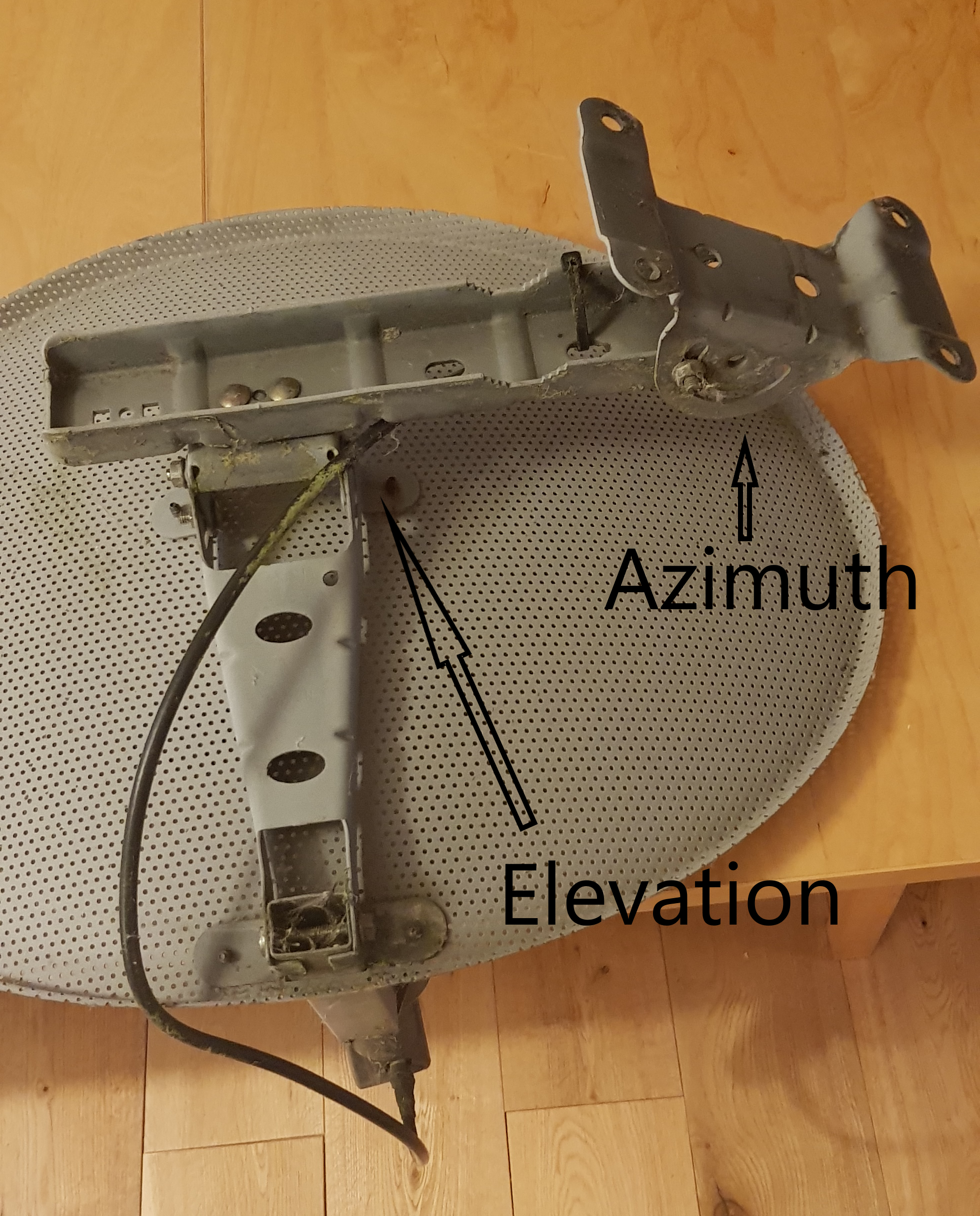
Attached to the back of the reflector is a mounting system. This is a double axis mount allowing for movement in azimuth (horizontal) and elevation (vertical) so the dish can be properly lined up to point at the satellite after installation. Again, this is great for getting a perfect TV signal and means the installer has some ability to align the dish after the large mounting holes have been drilled into the brick.
Along with the actual satellite dish we also removed many meters of co-axial cable that snaked around the house from the dish to the entry point near the back door. This turned out to be pretty standard co-axial cable, a transmission line, used to carry the electromagnetic signal received with low losses and signal interference. In this picture you can see the metal conducting core, the plastic insulating layer and the surrounding conducting shield. This cable went from the back of the receiver on the reflector antenna taking the received signal straight to your set top box connected to your TV.

The dish itself is really interesting on closer inspection. The holes in the paraboloid part of the dish can be clearly seen and seem to be well finished on both sides of the dish. The ‘edge’ of the dish is formed by just bending the metal round into the required shape, but the actual edge is just unfinished cut metal. If this dish were designed to detect different frequencies, or a weaker signal, then the edge of the dish would have to be carefully designed and manufactured.
There are two large screws near the centre of the dish, which will definitely cause a disturbance with this part of the reflected signal. However, the disturbance will be small enough that it does not stop the dish from meeting the required specification, and the screws will make it a lot easier to assemble the system. A good example of pragmatism in design. Sometimes a design is too difficult to manufacture or install, so compromises have to be made. As long as the total sum of these compromises can be tolerated, then this is a very sensible approach. This means other details will have to be well specified, manufactured and installed, but hopefully these will be easier details to do this with.

At the front of the dish on the receiver arm there is a little spirit level that is used during set up to ensure the receiver is parallel with horizontal. This will ensure the co and cross polar signals are correctly aligned, and therefore signal is not lost. Putting the spirit level in situ will make this an easier task for the installer, and the correct alignment have a big impact on the amount of signal received which will offset issues with the screws in the dish.

The receiver, a low-noise block downconverter (LNB), sits on the end of the receiver arm which is at the focus of the parabolid of the reflector. In this picture the receiver is more clearly seen as the top of the plastic housing has been removed. You can see the cast metal housing of the receiver electronics, where this flares to make the feed horn, and the plastic radome on the top of the feed horn.

If you want to see inside the receiver and feed horn, then tune in next week as I will be cutting my way into the inside then.
I would like to add an apology for the large number of spiders I evicted from their home for the sake of science. I can only sympathise with satellite dish installers as to the number of spiders they must encounter on a daily basis.
If you want to learn more about reflector antennas then check out my blog post on reflector antennas: https://swamphen.co.uk/new-blog/2019/4/15/lets-talk-about-reflector-antennas
If you want to learn more about radomes then check out my blog post on radomes: https://swamphen.co.uk/new-blog/2019/5/20/choose-your-radome-wisely